Building an Alarm / Anti Theft Module system for my 1997 Ford Explorer
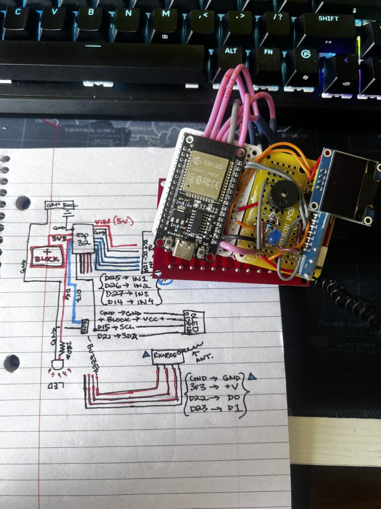
From Breadboard to Production Prototype!
Read About the Process Here!
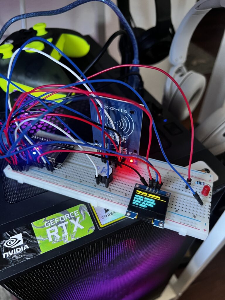
What began as a simple ESP32 breadboard prototype quickly evolved into one of the most valuable engineering exercises I’ve completed. The initial concept seemed straightforward—receive a wireless key fob signal, process it with an ESP32, drive relays, display system status on an OLED, and provide visual and audible feedback—but every stage of development introduced new challenges that required systematic troubleshooting. Throughout the build I encountered wiring mistakes, ground faults, failed solder joints, damaged ESP32 development boards, incorrect GPIO assignments, OLED communication failures, relay logic issues, and countless software bugs. Rather than replacing parts or guessing at solutions, I learned to isolate problems methodically by verifying power rails, checking continuity with a multimeter, tracing signal paths, validating GPIO states, monitoring serial output, and testing each subsystem independently before integrating the complete system.
The software side proved just as educational as the hardware. Using the Arduino framework, I developed firmware that manages wireless lock and unlock commands, relay control, OLED graphics, status LEDs, buzzer notifications, timing routines, debouncing, and power-saving features. Alongside the embedded programming, I continued strengthening my Python skills by documenting the project, organizing code revisions, and building supporting tools for future engineering work. One of the biggest lessons throughout the process was recognizing that successful embedded systems are built through disciplined iteration rather than writing perfect code on the first attempt. Every bug became another opportunity to better understand microcontrollers, digital electronics, serial communication, and software architecture.
This hand-wired prototype represents far more than a functioning vehicle alarm module—it represents the engineering process itself. Every solder joint, jumper wire, code revision, and debugging session contributed to a deeper understanding of electronics design, embedded programming, circuit integration, and practical problem solving. The experience reinforced the importance of patience, documentation, and structured troubleshooting, while providing a strong foundation for future projects involving custom PCBs, embedded systems, IoT devices, and automotive electronics. Looking back, the countless hours spent debugging were not setbacks; they were the most valuable part of the build, transforming a simple idea into a reliable, fully functional engineering project.
UPDATE: July 19,2026 – The Module w/ FOB logic is complete!
Next: Install and Final CAD modeling…
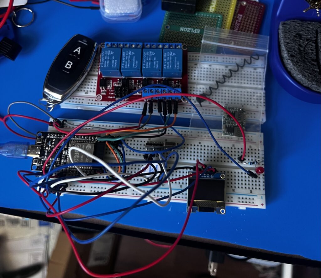
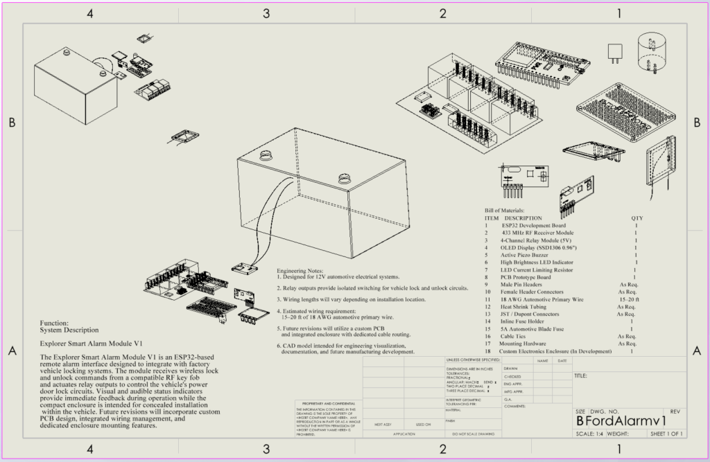
Development Log
Concept
The Explorer Smart Alarm Module began as a personal challenge to design an automotive security system around inexpensive hardware while learning embedded systems, PCB design, and software engineering.
The objective was never simply to create an alarm. The goal was to understand the engineering process required to transform an idea into reliable hardware capable of operating in a real vehicle.
Phase 1
Breadboard Prototype
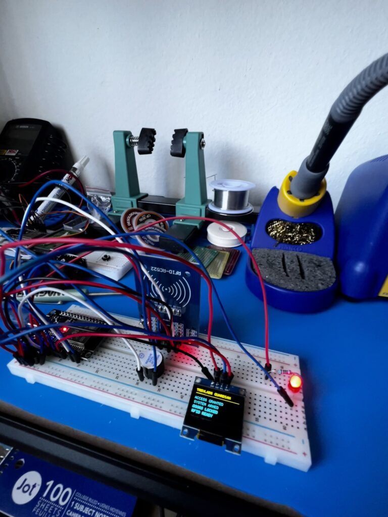
The first milestone was proving that an ESP32 could communicate with an RFID reader while driving an OLED display, LEDs, relays and a buzzer simultaneously.
Nothing worked perfectly the first time.
Initial testing revealed numerous wiring mistakes, incorrect pin assignments and intermittent communication failures that required careful troubleshooting before any software bugs could even be identified.
Electrical Challenges
Throughout development several electrical issues appeared that forced complete redesigns.
• Misidentified GPIO pins
• Incorrect relay wiring
• Ground loops causing unstable behavior
• Loose jumper wire connections
• Breadboard power distribution problems
• Shared grounds introducing random resets
Each problem required isolating one subsystem at a time before reconnecting the complete system.
One of the biggest lessons learned was that software often receives blame for problems that ultimately originate in hardware.
Hardware Failures
Development was not without casualties.
During testing one ESP32 development board was permanently damaged after an electrical fault.
Although frustrating, replacing the controller became an important reminder that rapid prototyping often includes hardware failures, and protecting electronics with proper wiring practices is just as important as writing reliable code.
Software Development
The software evolved through dozens of revisions.
Features included:
• RFID authentication
• OLED status interface
• Alarm armed/disarmed state management
• Relay control logic
• Audible feedback
• Visual status indicators
As functionality increased, maintaining clean state logic became increasingly important to prevent unexpected behavior during testing.
Many revisions were dedicated entirely to improving reliability rather than adding new features.
Waiting Between Iterations
Progress rarely occurred in a straight line.
Several stages required waiting for replacement components, relays, connectors, RFID modules and additional electronics to arrive before testing could continue.
Rather than stopping development, these delays became opportunities to redesign hardware layouts, improve software structure and prepare future revisions.
Engineering often involves solving today’s problems while planning tomorrow’s improvements.
Transition to Wireless
After validating the original RFID concept, the project evolved toward a more practical automotive solution.
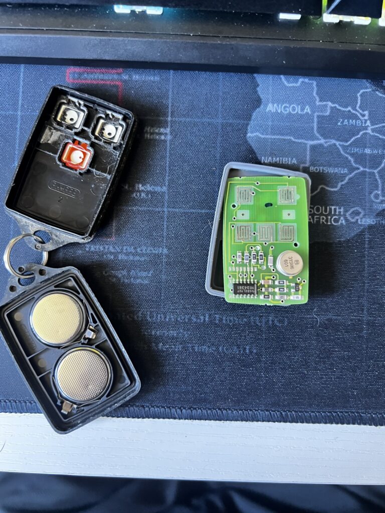
A wireless key fob receiver replaced the RFID authentication process, allowing the system to operate much more like a factory-installed vehicle alarm.
This transition required significant changes to the input handling logic while preserving the underlying state machine developed throughout earlier revisions.
Looking Ahead
The current prototype demonstrates the complete functional concept, but several improvements remain planned.
Future revisions include:
• Custom PCB design
• 3D printed enclosure
• Automotive-grade connectors
• Integrated wire routing
• Conformal coating
• Vehicle installation testing
• Low-power sleep mode
• CAN bus expansion
Each revision moves the project closer to a production-quality embedded automotive module.
Lessons Learned
This project reinforced one lesson above all others:
Engineering is rarely about getting everything right on the first attempt.
Reliable systems are created through repeated testing, failures, redesigns and incremental improvements.
Every burned component, wiring mistake, software bug and delayed shipment became part of the engineering process.
The finished prototype is ultimately the result of dozens of small iterations rather than one successful build.
Development Timeline
V1
- Initial ESP32 + RFID proof of concept
- Basic relay and buzzer operation
↓
V2
- Software refinement
- Wiring improvements
- Hardware troubleshooting
- State-machine redesign
↓
V3
- Wireless key fob integration
- Final control logic
- Automotive-ready prototype
- Functional system demonstration
Update to the Ford Alarm Module: July 11, 2026 – the relays came in the mail and now I am just waiting on the buck converter to start the install plans into the vehicle.
PROJECT
Explorer Alarm Module
STATUS
Prototype Rev A
CONTROLLER
ESP32
POWER
12V Automotive
Buck Converter
FEATURES
RFID Authentication
Relay Outputs
LED Indicators
Audible Alarm
Custom Firmware
CAD
SolidWorks
FIRMWARE
Arduino (C++)
PROJECT START
2026
STATUS
In Active Development
Building Cyclo v1
Cyclo didn’t begin as a trading terminal.
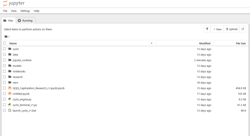
It started as a collection of Python scripts, research notebooks, spreadsheets, and questions about how markets behave beneath the surface. The goal wasn’t simply to build another dashboard—it was to create a research environment capable of studying dealer positioning, volatility, market structure, options flow, liquidity, and intraday behavior through repeatable engineering.
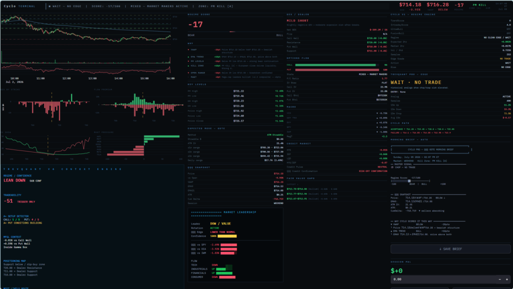
Every feature shown in Cyclo today was built from scratch through continuous experimentation. Data pipelines were designed, historical databases organized, models tested, interfaces rebuilt, and hundreds of revisions made before arriving at the current platform.
This page documents that engineering journey.
From the first lines of Python code to the latest version of the research terminal, these screenshots capture the progression of an idea becoming a working system.
Cyclo remains an active project, and every revision brings new research, better models, cleaner code, and a deeper understanding of market structure.
Development Timeline
Phase 1 – Research Foundation
Learning Python, collecting market data, experimenting with historical analysis, and understanding how market structure could be quantified.
Phase 2 – Data Engineering
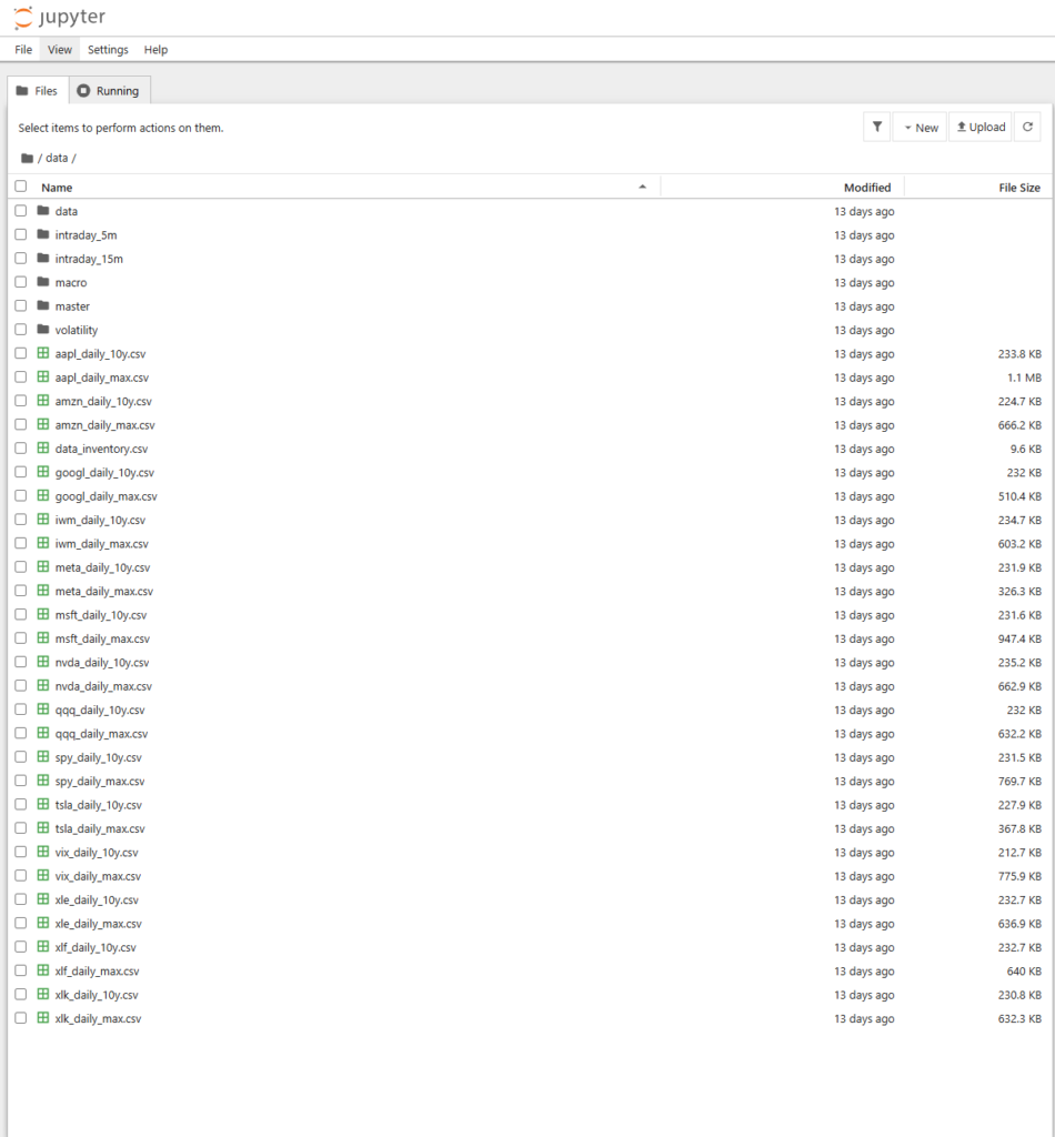
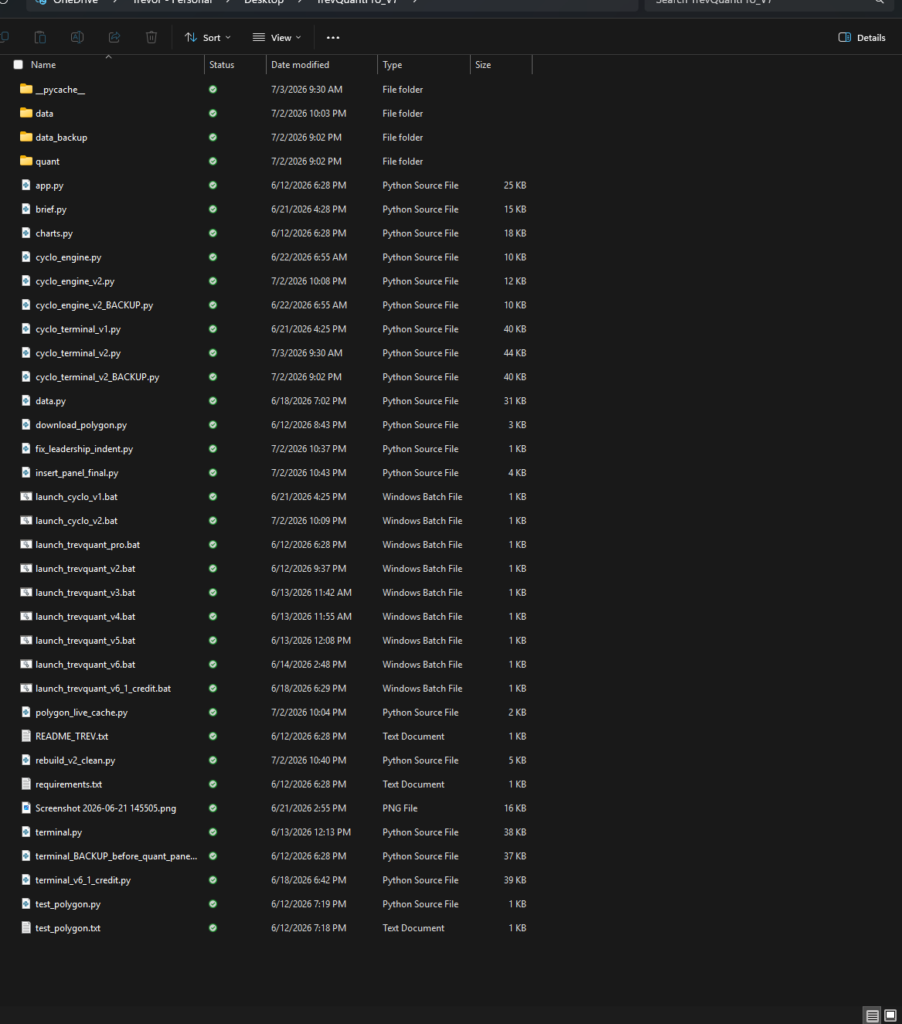
Building data pipelines, organizing years of historical datasets, cleaning information, and creating reusable research databases.
Phase 3 – Quantitative Models
Developing scoring engines, dealer positioning models, expected move calculations, volatility analytics, and regime detection.
Phase 4 – Terminal Development
Bringing every subsystem together into a single research environment capable of supporting daily market analysis.
Phase 5 — Continuous Development
Cyclo is still evolving.
Current work includes:
- Improved market regime detection
- Additional quantitative models
- Faster data pipelines
- Live options analytics
- Better visualizations
- Machine learning research
- Automated Morning Brief generation
Engineering is iterative.
Cyclo v1 wasn’t built in a weekend—it represents hundreds of hours of research, programming, debugging, redesigning, and testing. Every version documents another step toward building a better quantitative research platform.
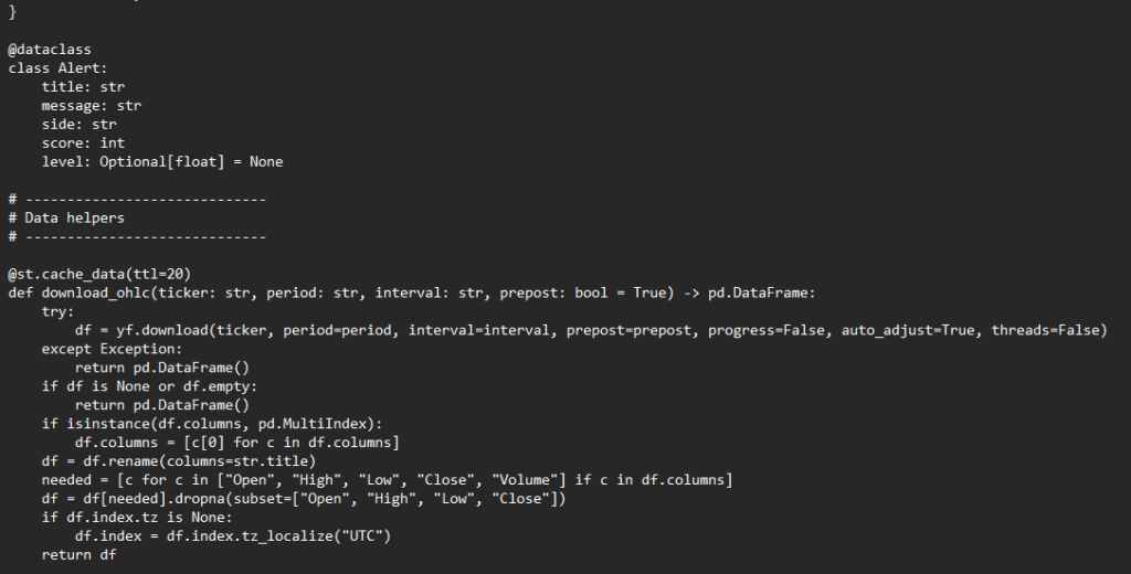
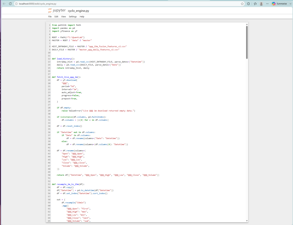
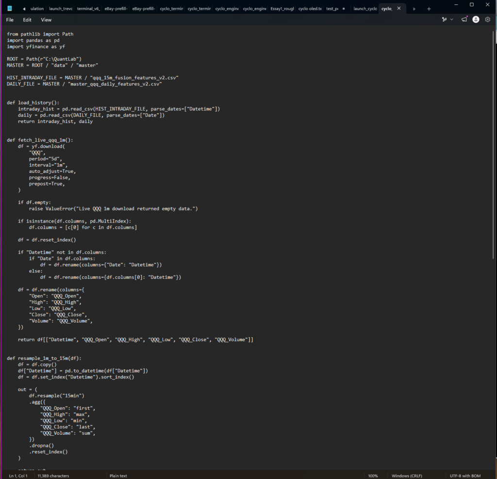
First my scanners started off small, pulling live data only… boy what I’d come to later realize the efficiency of a conglomerate of historical and live data being read in a mathematical model.
Here are two examples of scripts that work off both historic and live data feeds.